.
.Parts of the Camera
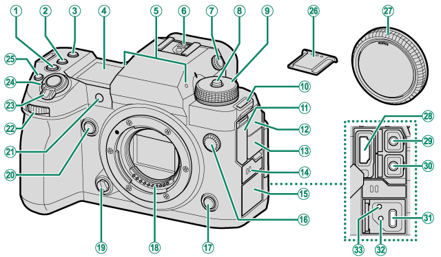
AISO button
BWB button
CFn1 button
DSecondary LCD monitor
EMicrophone
FHot shoe
GDiopter adjustment control
HDial lock release
IMode dial
JStrap eyelet
KHDMI connector cover
LMicrophone jack cover
MHeadphone jack cover
NSpeaker
OUSB connector cover
PSync terminal
QFn3 button
RLens signal contacts
SLens release button
TFn2 button
UAF-assist illuminator
Self-timer lamp
Tally light
VFront command dial
WON/OFF switch
XShutter button
Yt (movie recording) button
ZHot shoe cover
aBody cap
bHDMI connector (Type A)
cMicrophone jack (Φ3.5mm)
dHeadphone jack (Φ3.5mm)
eUSB connector (Type-C)
fHole to screw USB cable
gHole to screw cable protector
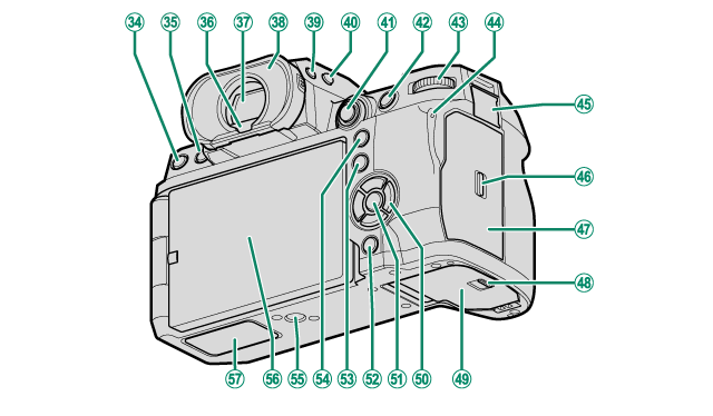
hDRIVE button
b (delete) button
ia (playback) button
jEye sensor
kElectronic viewfinder (EVF)
lEye cup (lockable)
mVIEW MODE button
nSecondary monitor backlight button
oFocus stick (focus lever)
pAFON button
qRear command dial
rIndicator lamp
Tally light
sRemote release connector cover
tMemory card slot cover latch
uMemory card slot cover (detachable)
vBattery-chamber cover latch
wBattery-chamber cover
xSelector buttons
yMENU/OK button
zDISP (display)/BACK button
x (Bluetooth) button
0Q (quick menu) button
1AEL (exposure lock) button
2Tripod mount
3LCD monitor
Touch screen
4File transmitter/vertical battery grip connector cover
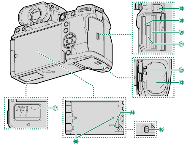
5Remote release connector (Φ2.5mm)
6Memory card slot 2 (for SD memory cards)
7Serial number plate
8Memory card slot 1 (for Type B CFexpress cards)
9Battery latch
-Battery chamber
^Cooling fan connector cover
\Cooling fan connector
$Hole to screw cooling fan
%File transmitter/vertical battery grip connector
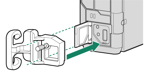
The Cable Protector
Attach the protector as shown to prevent accidental disconnection.
ASlide the protector over the USB connector cover so that the cover passes through the slot in the protector.
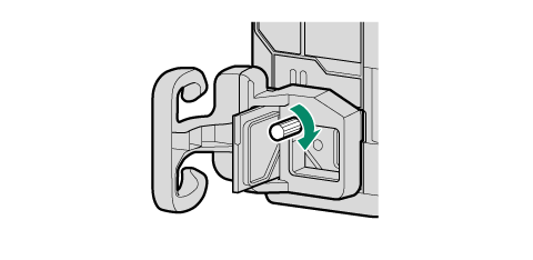
BTighten the lock screw.
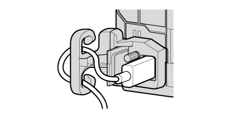
CConnect the cable and pass it through the protector as shown.
- The Serial Number Plate
- Memory card slot cover (Detachable)
- The Focus Stick (Focus Lever)
- The Selector
- The WB Button
- The Mode Dial
- The DRIVE Button
- The Command Dials
- The Indicator Lamp
- The LCD Monitor
- The Eye Cup
- Focusing the Viewfinder
The Serial Number Plate
Do not remove the serial number plate, which provides the CMIIT ID, serial number, and other important information.
Serial number plate
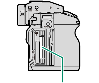
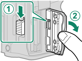
The Memory Card Slot Cover (Detachable)
The memory card slot cover can be removed by lowering the interior latch. Remove the cover for ease of access when a camera rig is attached or in other situations that make it difficult to open or close the cover.
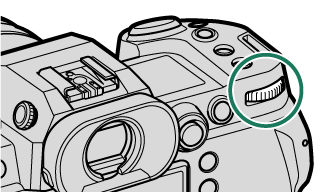
The Focus Stick (Focus Lever)
Tilt or press the focus stick to select the focus area. The focus stick can also be used to navigate the menus.
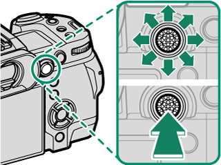
To choose the role played by the focus stick, press and hold the center of the stick or use DBUTTON/DIAL SETTING > FOCUS LEVER SETTING.
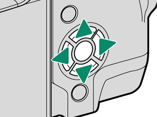
The Selector
Press the selector up (e), right (h), down (f), or left (g) to highlight items. The up, right, down, and left buttons also double as function buttons Fn4 through Fn7.
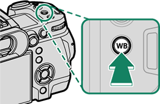
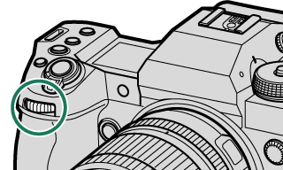
The WB Button
Press the WB button to access white balance settings.
The Mode Dial
To select a shooting mode, rotate the dial until the icon for the desired mode aligns with the index.
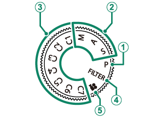
| Mode | Description |
|---|---|
| Aperture and shutter speed can be adjusted using program shift. | |
| Select for full control over camera settings, including aperture (M and A) and/or shutter speed (M and S). | |
| Take pictures using previously-stored settings. | |
| Take photos with filter effects. | |
| Record movies. |
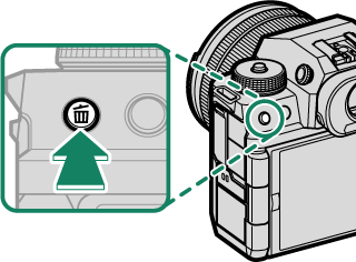
The DRIVE Button
Press the DRIVE button displays drive-mode menu, where you can choose from the following the drive modes.
| Mode | |
|---|---|
| B | Single frame |
| J | High-speed burst |
| J | High-speed burst (1.25X crop) |
| O | Low-speed burst |
| W | ISO BKT |
| V | WHITE BALANCE BKT |
| BKT | Bracketing |
| h | HDR |
| u | Panoramas |
| j | Multiple Exposure |
The Command Dials
The rear and front command dials are used for the operations below.
| Shooting 1 | P | Choose the desired combination of shutter speed and aperture (program shift). |
|---|---|---|
| S | Choose a shutter speed. | |
| A | Adjust aperture. 2 | |
| M | Adjust aperture. 2 | |
| FILTER | Program shift. | |
| Menus | Select menu tabs or page through menus | |
| Q Menu | Select items in the quick menu. | |
| Playback | View other pictures | |
| Shooting 1 | P | Adjust exposure compensation. |
|---|---|---|
| S | ||
| A | ||
| M | Choose a shutter speed. | |
| FILTER | Adjust exposure compensation. | |
| Menus | Highlight menu items | |
| Q Menu | Adjust settings in the quick menu | |
| Playback |
|
|
1 Settings for FRONT COMMAND DIAL 1, FRONT COMMAND DIAL 2, FRONT COMMAND DIAL 3, and REAR COMMAND DIAL can be changed using DBUTTON/DIAL SETTING > COMMAND DIAL SETTING.
2 Applies if the lens has no aperture ring or if an aperture ring with an “A” position is in the A position.
The rotation direction for the command dials can be selected using DBUTTON/DIAL SETTING > COMMAND DIAL DIRECTION.
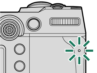
The Indicator Lamp
Camera status is shown by the indicator lamp.
| Indicator lamp | Camera status |
|---|---|
| Glows green | Focus locked. |
| Blinks green | Focus or slow shutter speed warning. Pictures can be taken. |
| Blinks green and orange | Camera on: Recording pictures, or picture displayed for confirmation after being taken with option other than OFF selected for DSCREEN SETTING > IMAGE DISP. (additional pictures can be taken). |
| Camera off: Uploading pictures to a smartphone or tablet. * | |
| Glows orange | Recording pictures. No additional pictures can be taken at this time. |
| Blinks orange | Flash charging; flash will not fire when picture is taken. |
| Blinks red | Lens or memory error. |
* Displayed only if pictures are selected for upload.
Warnings may also appear in the display.
The indicator lamp remains off while your eye is to the viewfinder.
The BMOVIE SETTING > TALLY LIGHT option can be used to choose the lamp (indicator or AF-assist) that lights during movie recording and whether the lamp blinks or remains steady.
The LCD Monitor
You can adjust the angle of the LCD monitor when framing shots, but be careful not to trap your fingers or other objects.

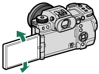
Do not apply excessive force to the hinge when rotating the LCD monitor, as this could damage the hinge.
Be careful that the corners of the monitor do not contact the camera body, as this could leave marks.
The LCD monitor also functions as a touch screen that can be used for:
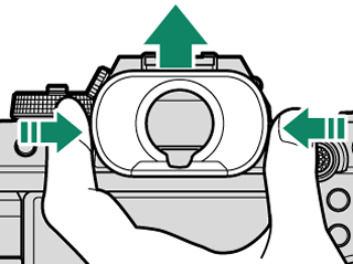
The Eye Cup
To remove the eye cup, hold the buttons on either side and slide eye cup up.
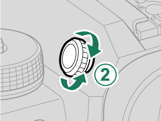
Focusing the Viewfinder
If the indicators displayed in the viewfinder are blurred, put your eye to the viewfinder and rotate the diopter adjustment control until the display is in sharp focus.
To focus the viewfinder:
ALift the diopter adjustment control.
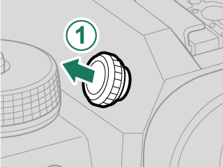
BRotate the control to adjust viewfinder focus.
CReturn the control to its original position and lock it in place.
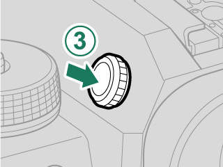
Lift the control before use. Failure to observe this precaution could cause product malfunction.